In image processing and computer vision, edge detection is often a vital task. As the name suggests, edge detection refers to finding edges—that is, boundaries between regions or objects. This is not a trivial process, and there exist many techniques for finding edges. One of the earliest and most well-known approaches involves the Sobel operator, which dates back to 1968. Developed by Irwin Sobel and Gary Feldman, it is sometimes also called the Sobel-Feldman operator. The basic idea behind the Sobel operator is to quantify the rate of change of the pixel intensities throughout an image. In other words, it seeks to calculate the spatial derivative of each pixel in the image. At the boundary between objects or regions in an image, there is usually a rapid shift in pixel intensities. Consequently, the magnitude of the derivative at these boundaries tends to be relatively large. Finding the areas in an image with a large derivative can provide insight into the locations of edges and contours.
This post assumes that you already understand the concept of kernels as they relate to image processing, and also that you understand how images are represented digitally. If these concepts are not familiar to you, you should read the previous post on kernels and images: Kernels in image processing
Furthermore, if you’d like, you can read the original letter on the subject written by Irwin Sobel. The short letter presents the topic far more concisely than this post. However, the goal of this post is not to be concise. Rather, it is to lay the concept (and its derivation) out in a little more detail.
Deriving the Sobel kernels
An image is not continuous but, rather, consists of distinct pixels. That means we aim to compute a discrete approximation to the derivative for each pixel. Traditionally, the Sobel technique considers a 3×3 pixel neighborhood. We can represent the pixels in this 3×3 neighborhood with the letters \(a\) through \(i\), like so:
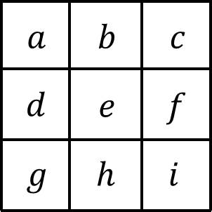
In this figure, the pixel of interest is the central pixel, pixel \(e\). The other 8 pixels, \(a\), \(b\), \(c\), \(d\), \(f\), \(g\), \(h\) and \(i\), are its surrounding neighborhood pixels. The goal is to approximate the derivative at \(e\) based on the intensities of all the pixels in the neighborhood. A spatial derivative is simply the difference in pixel intensity between two pixels divided by the distance between those pixels. If we consider the distance between directly adjacent pixels to be 1, this can be illustrated as follows:
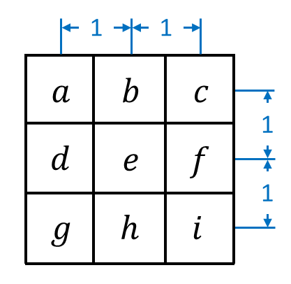
This might be easier to visualize, geometrically, if we represent the pixel centers as nodes and the distance between them with lines:
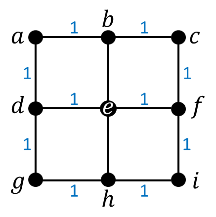
Then, computing the derivative of the central pixel is a matter of computing the sum of the directional derivative with respect to each of the 8 surrounding pixels:
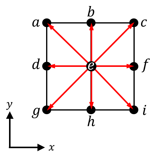
In the figure above, the 8 directional derivatives are represented with red arrows. Note the coordinate system; by describing the pixel neighborhood with respect to an xy coordinate system, we can compute the directional derivatives in terms of their x and y components. For example, the directional derivative between the central pixel \(e\) and the pixel to its right, pixel \(f\), is given by \((f-e)\pmb{\hat{\imath}}\), where \(\pmb{\hat{\imath}}\) is the unit vector in the positive x direction, and \(e\) and \(f\) represent the pixel intensities of pixels \(e\) and \(f\), respectively. The directional derivative between the central pixel and the pixel to its left, pixel \(d\), is given by \(-(d-e)\pmb{\hat{\imath}}\). Recall that the derivative is equal to the difference in pixel intensities divided by the distance between the pixels; in this case, the distance between the pairs of pixels happens to be 1.
Similarly, the directional derivative between \(b\) and \(e\) is given by \((b-e)\pmb{\hat{\jmath}}\), where \(\pmb{\hat{\jmath}}\) is the unit vector in the positive y direction. The directional derivative between \(e\) and \(h\) is given by \(-(h-e)\pmb{\hat{\jmath}}\). Again, the distance between these pairs of pixels is 1.
What about the diagonal directional derivatives? Consider the vector between \(c\) and \(e\), which forms an isosceles right triangle whose hypotenuse has length \(\sqrt{2}\):
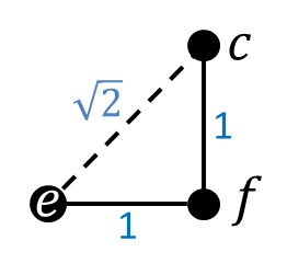
Then the directional derivative, which possesses both an x and y component, is:
\[\frac{1}{\sqrt{2}} [(c-e)\cos45^\circ \pmb{\hat{\imath}} + (c-e)\sin45^\circ \pmb{\hat{\jmath}} ]\]
Recognizing that \(\cos45^\circ = \sin45^\circ = \frac{1}{\sqrt{2}}\), we can simplify this to:
\[\frac{1}{2}(c-e)(\pmb{\hat{\imath}} + \pmb{\hat{\jmath}})\]
Doing the same for the remaining derivatives and summing all 8, we find that the terms involving \(e\), the central pixel, conveniently cancel out, leaving us with:
\[[(f-d) + \frac{1}{2}(-a+c-g+i)]\pmb{\hat{\imath}} \\ +[(b-h) + \frac{1}{2}(a+c-g-i)]\pmb{\hat{\jmath}}\]
From this, we see that summing all 8 directional derivatives produces an x component (\(\pmb{\hat{\imath}}\)) and a y component (\(\pmb{\hat{\jmath}}\)). If we write these out as kernels, with \(G_x\) representing the x component and \(G_y\) representing the y component (the derivative of a vector-valued function is also called the “gradient,” which is where the “G” comes from), the kernels look like this:
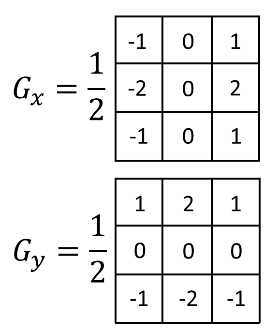
Per Sobel’s original paper, because 8 pixels are used to compute the overall gradient, the kernels should be multiplied by \(\frac{1}{8}\), resulting in a total factor of \((\frac{1}{8}) (\frac{1}{2}) = \frac{1}{16}\). However, traditionally, this factor is dropped, leaving the following:
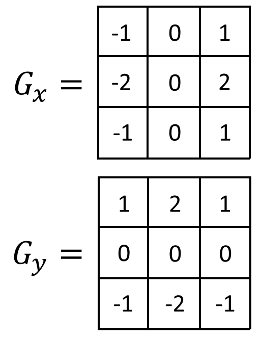
These are the traditionally used Sobel kernels (also known as the Sobel operator). If we wanted the actual gradients, though, we would have to include the factor of \(\frac{1}{2}\). Or, if we wanted the actual average gradient, we would have to include the factor of \(\frac{1}{16}\).
The overall gradient \(G\) for any given pixel is the magnitude of the sum of \(G_x\) and \(G_y\):
\[G = \sqrt{G_x^2 + G_y^2}\]
Visualizing the Sobel gradient
What does it look like when we actually apply the Sobel kernels to an image? First, let’s take a look at a sample source image:

To detect edges via the Sobel operator, the image should generally be converted to a single channel, hence the grayscale. Furthermore, since the Sobel kernels consider only the neighboring pixels in the immediate vicinity of any given pixel, they are susceptible to noise. Consequently, a smoothing filter, like box blur or Gaussian blur, is usually applied to the original image before it’s processed by the Sobel kernels. To illustrate this point, let’s first observe what happens when the Sobel operator is applied to the raw image without smoothing:
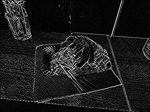
Not bad—notice how the edges are clearly highlighted. Still, there’s a lot of noise that distracts from the real edges, particularly due to the pattern of the wood grain on the table. We can improve this somewhat by first applying a 3×3 Gaussian blur to the image:
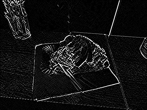
This is better. What if we increase the size of the Gaussian blur kernel to 5×5? The result is as follows:
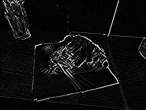
The edges are more defined still, though there appear to be diminishing returns. It should also be noted that using a Gaussian blur as opposed to a box blur, or increasing the size of the smoothing kernel, increases processing time. This may not be an issue for a single image, but can certainly be a concern for real-time video processing or for processing large batches of images. Along similar lines, note that larger Sobel kernels (e.g., 5×5) can also be implemented. The derivation for these larger Sobel kernels is slightly more involved, since there are more directional derivatives, but the approach is identical.
Conclusion
While the Sobel operator is a valuable tool for edge-detection, it is only one of several commonly used methods. Furthermore, while this technique can help isolate the edges in an image, additional processing is required to determine which edges form contours or to determine the shapes of those contours. We will likely revisit this topic again at some point, and discuss some of these other techniques.
